OFF CENTER TUNING YOUR CB ANTENNA
Compliments of Firestik® Antenna Company Technical Support Team
Copyright © 1996 Firestik® Antenna Company
|
The normal recommended procedure for tuning a CB antenna instructs you to check standing wave ratio (SWR) on Channels 1 and 40 and use that information to determine if the antenna is electrically long or electrically short. See our article "Setting the SWR of your Antenna". You are further advised that your goal is to adjust the antenna so that the SWR on Channels 1 and 40 are the same value. When you do that, the SWR will be at its lowest point (the dip) at or about Channel 19. The reason for this method would be to allow you to have the best SWR scenario across all 40 CB channels. But, what if you do not use all CB channels? For instance, suppose the majority of your conversations take place on channel 5, or 10, or 30, etc.. You can tune your antenna with the dip in a place other than channel 19. Likewise, if the antennas bandwidth has the SWR too high at the channel extremes, you can increase the efficiency of the system by shifting the resonant point somewhere else. For all intents and purposes, a transmitting antenna will be resonant at one specific frequency. This is the frequency where you will generally find the lowest SWR and realize the highest effective radiated power. If you want to zero in on a specific channel, that is, have the maximum effective radiated power on a specific channel, simply tune your antenna so that your SWR is lowest on that channel. The process is similar to the standard method. Suppose you wanted your SWR to dip on channel 30. In that case, check SWR on channel 20 (10 channels down) and on Channel 40 (10 channels up) and adjust the SWR until it is the same on both channels. This will, in effect, put the SWR dip at or about channel 30. Likewise, if you wanted the dip to occur on Channel 12, you might use Channel 1 (down 12 channels) and channel 24 (up 12 channels) as your reference points. For other channels, just move up and down the same amount of channels from your desired dip point and use those channels as your reference points. In any case, with the dip positioned at channel 19, making the antenna electrically (not physically) longer will move the dip towards the lower channels and making it electrically (not physically)shorter will shift the dip towards the higher channels. Here are a couple of SWR charts that may offer you a visual depiction of what this procedure is about. These charts are made for the purpose of visualizing the off-center tuning concept. You actual readings can vary. The green band shows the channel coverage at 2.0:1 SWR and lower, the yellow band show the 2.0:1 to 3.0:1 channels and the red band is the over 3.0:1 danger zone. This chart shows the SWR curve that used channels 1 and 40 as the reference points for tuning. The antenna, perhaps because it is a very short (physically) antenna that it does not have a lot of bandwidth. You can see that the SWR on the channel extremes is between 2.5:1 and 3.0:1. 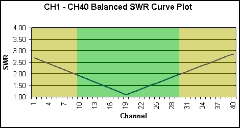 Suppose you are like many users and only use the lower 20 channels. To improve efficiency in the channel 1 to 20 range with the same antenna depicted in the above chart, you can shift the resonant frequency over to channel 10 by balancing the SWR on channels 1 & 20. That offers maximum efficiency across the lower 20 channels that this user uses, allows for safe transmitting up to about channel 30 but, restricts transmitting [not receiving] on the 10 highest numbered channels. 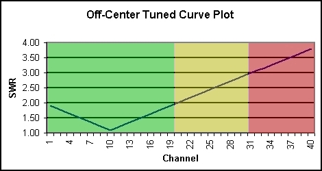 AN SWR plotting graph in PDF format is available from Firestik to assist you with your tuning activities. You can print copies of it on your printer. Click here to access the graph. |

Updated: 2023.12.05